Jack Zhang.
§ Portfolio / 2023—2026
Rev. 03 · Updated May 2026
Toronto, ON
Available — 12-mo PEY · Sept 2026

Mechanical
engineering
with a bias for building.

Third-year mech eng at the University of Toronto, specializing in mechatronics and solid mechanics. Most of what I do starts as a CAD file and ends as something physical. The interesting part is everything in between.

§ 01 / Selected Work

Things I've designed, built, and broken.

01
Year
2024—25
Type
Personal · Thermal Systems
Tools
Fusion 360 · Klipper · GD&T
Status
Operational

A 4-axis enclosed 3D printer that prints polycarbonate reliably.

The problem. Polycarbonate (PC and PC-CF) is a structural-grade thermoplastic, but the temperature gradient between extrusion and ambient causes warping and delamination. To print PC reliably, the chamber needs to hold ~80 °C steady-state — well above what an off-the-shelf printer can do.

What I built. An integrated thermal management system on a custom-built CoreXY printer: reflective insulation lining, dual 5015 blowers under the bed for forced convection, and a 100 W PTC chamber heater module mounted to the lower wall.

Architecture · in order of operations
01 · Insulation
Minimize loss
Reflective foil lining on all six interior surfaces. Establishes the thermal boundary.
02 · Bed fans
Distribute existing heat
Dual 5015 blowers under a 150 W bed. Forced convection scrubs heat into the chamber.
03 · PTC heater
Add the residual
100 W active heater sized to overcome remaining steady-state loss.
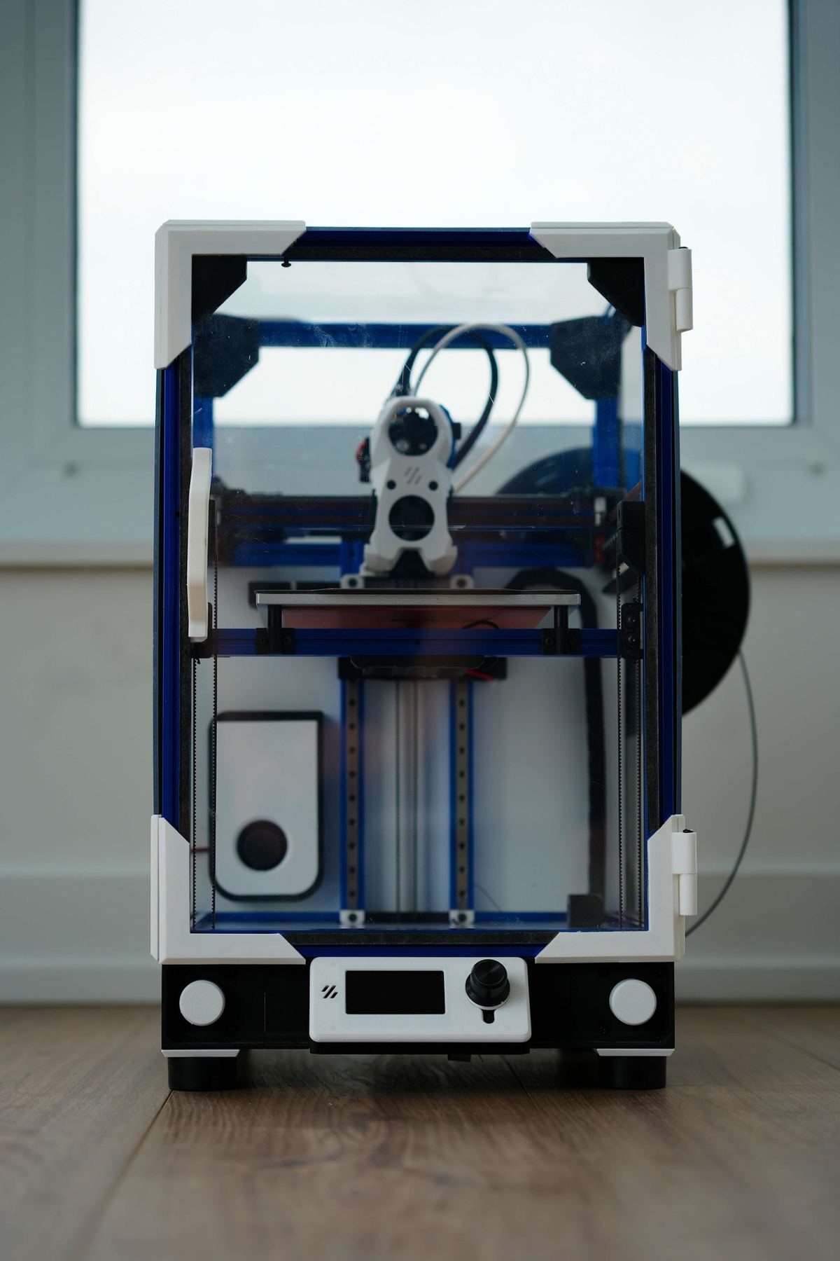
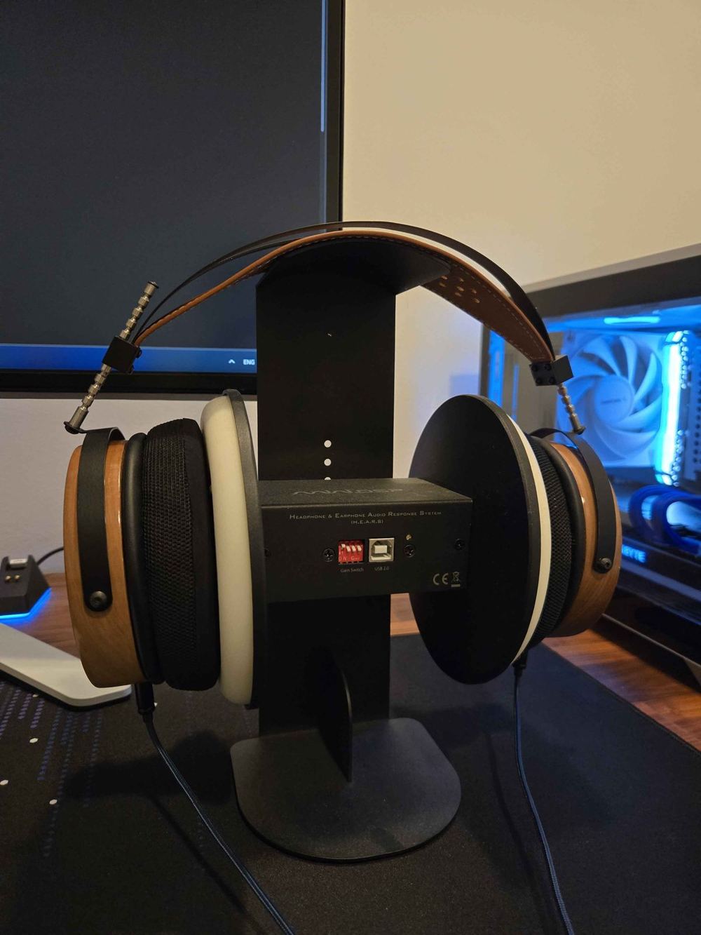
Front view of the completed enclosed 3D printer
FIG. A1
Completed printer. Custom acrylic enclosure with PETG corner brackets, 235×235 mm bed, full thermal management stack visible through the front panel.
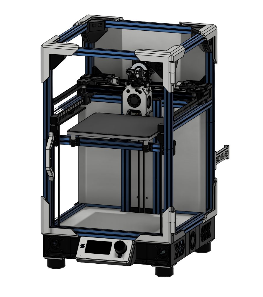
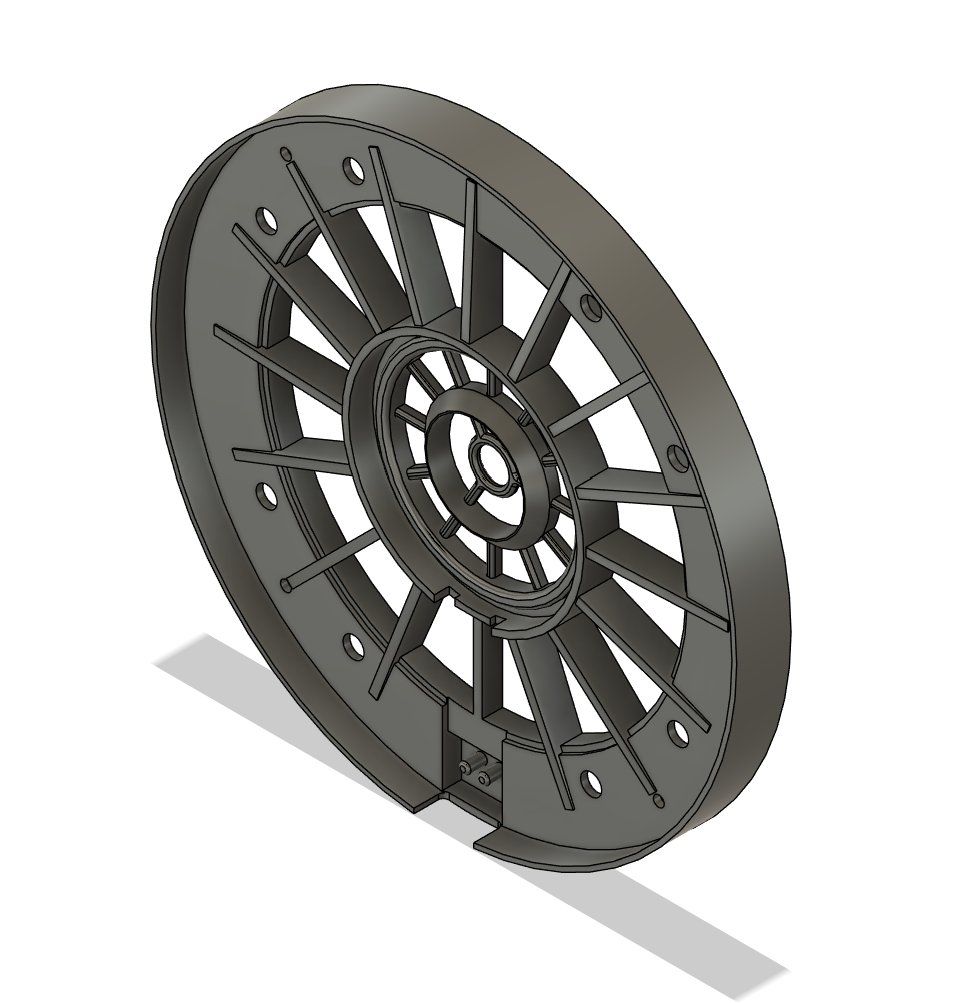
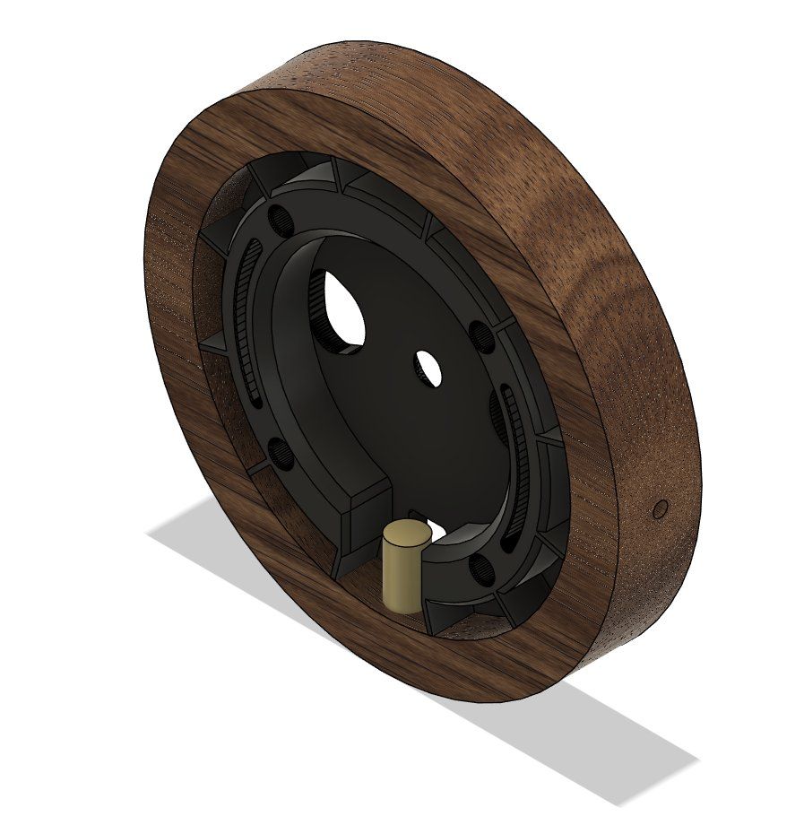
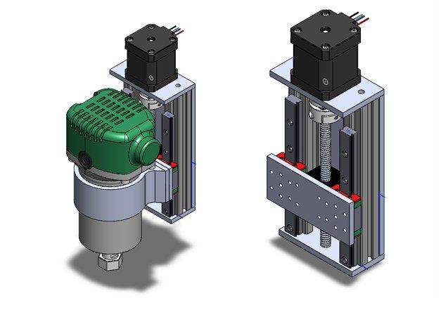
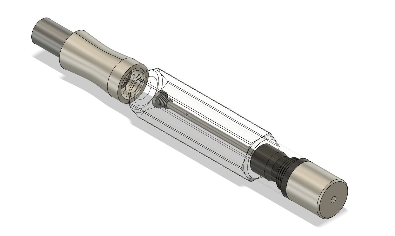
CAD model of the printer enclosure
FIG. A2
Fusion 360 assembly. Aluminum extrusion frame with kinematic-coupled bed mounts.
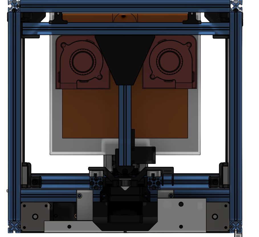
Internal CAD view showing dual bed fans
FIG. A3
Dual 5015 blowers mounted beneath the 150 W heated bed scrub heat into the chamber.
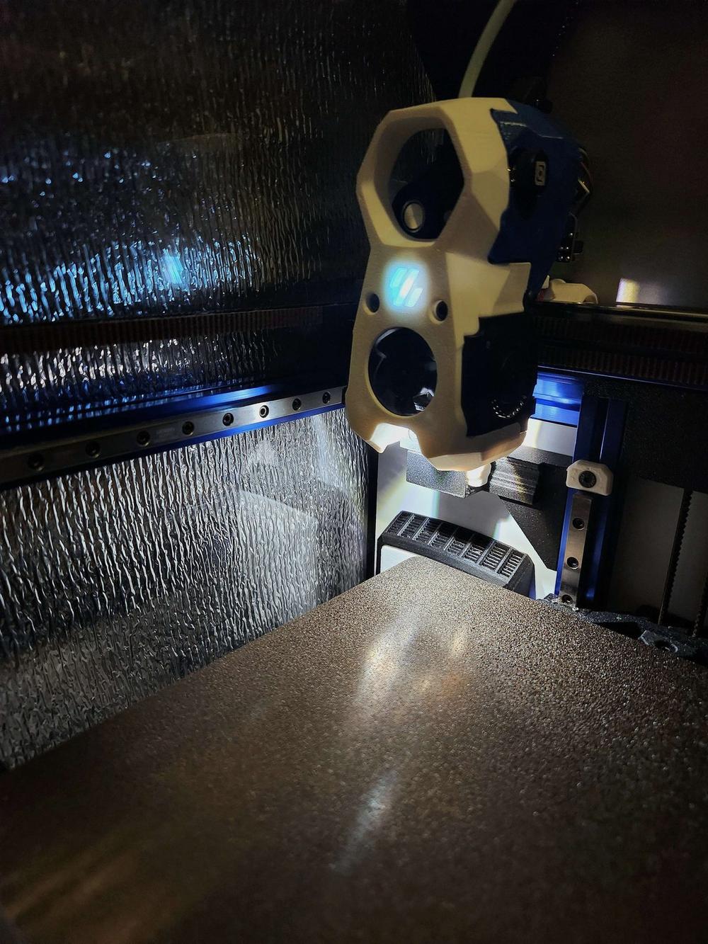
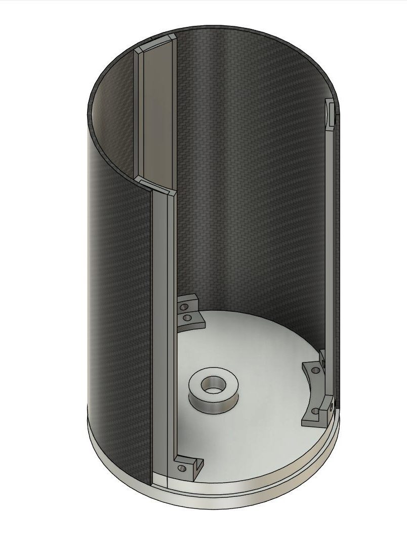
Toolhead inside the lined chamber, foil insulation visible
FIG. A4
Inside the chamber. Reflective foil insulation lines all interior surfaces, establishing the thermal boundary.
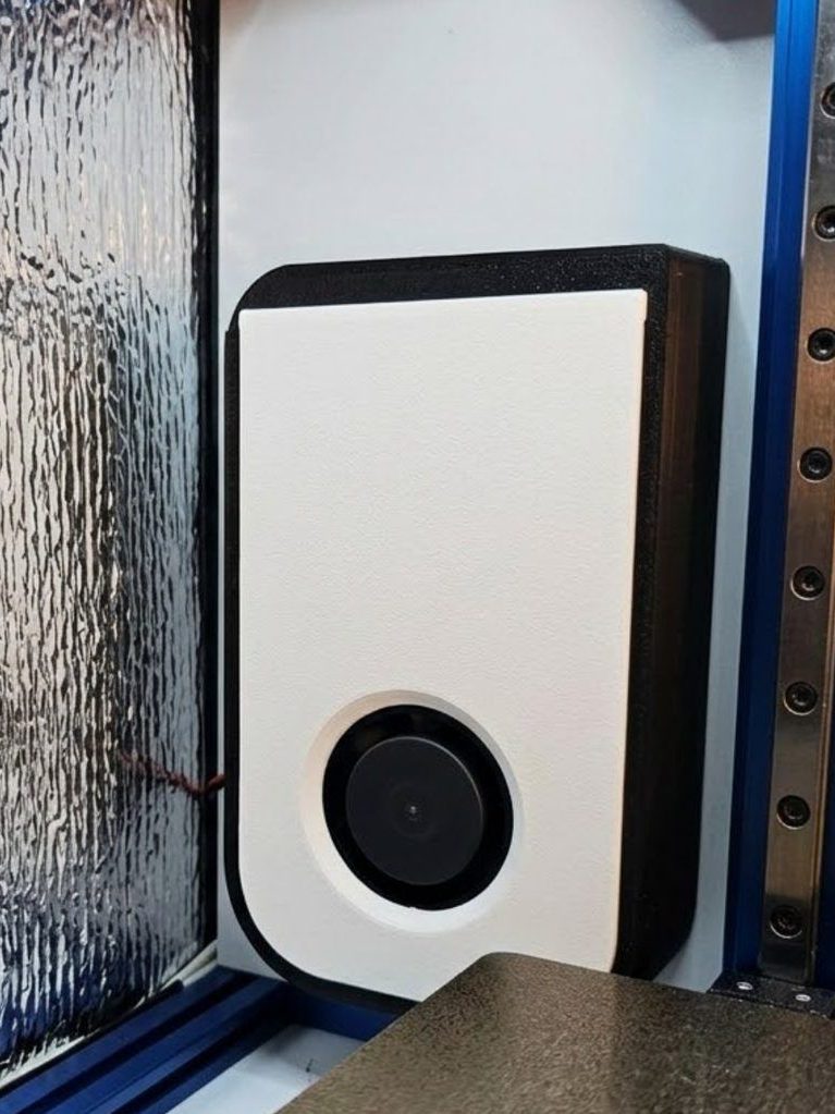
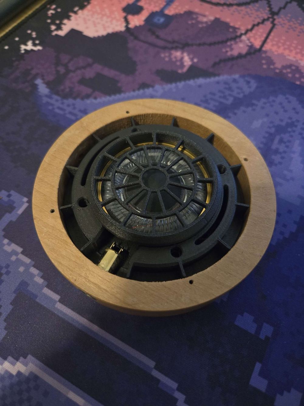
The 100W PTC chamber heater module mounted in the chamber
FIG. A5
The chamber heater module: 100 W PTC element + 5015 blower in a 3D-printed shroud.

→ Result

80°C
Steady-state chamber temp
15min
Time to thermal equilibrium
PC/CF
Materials now printable
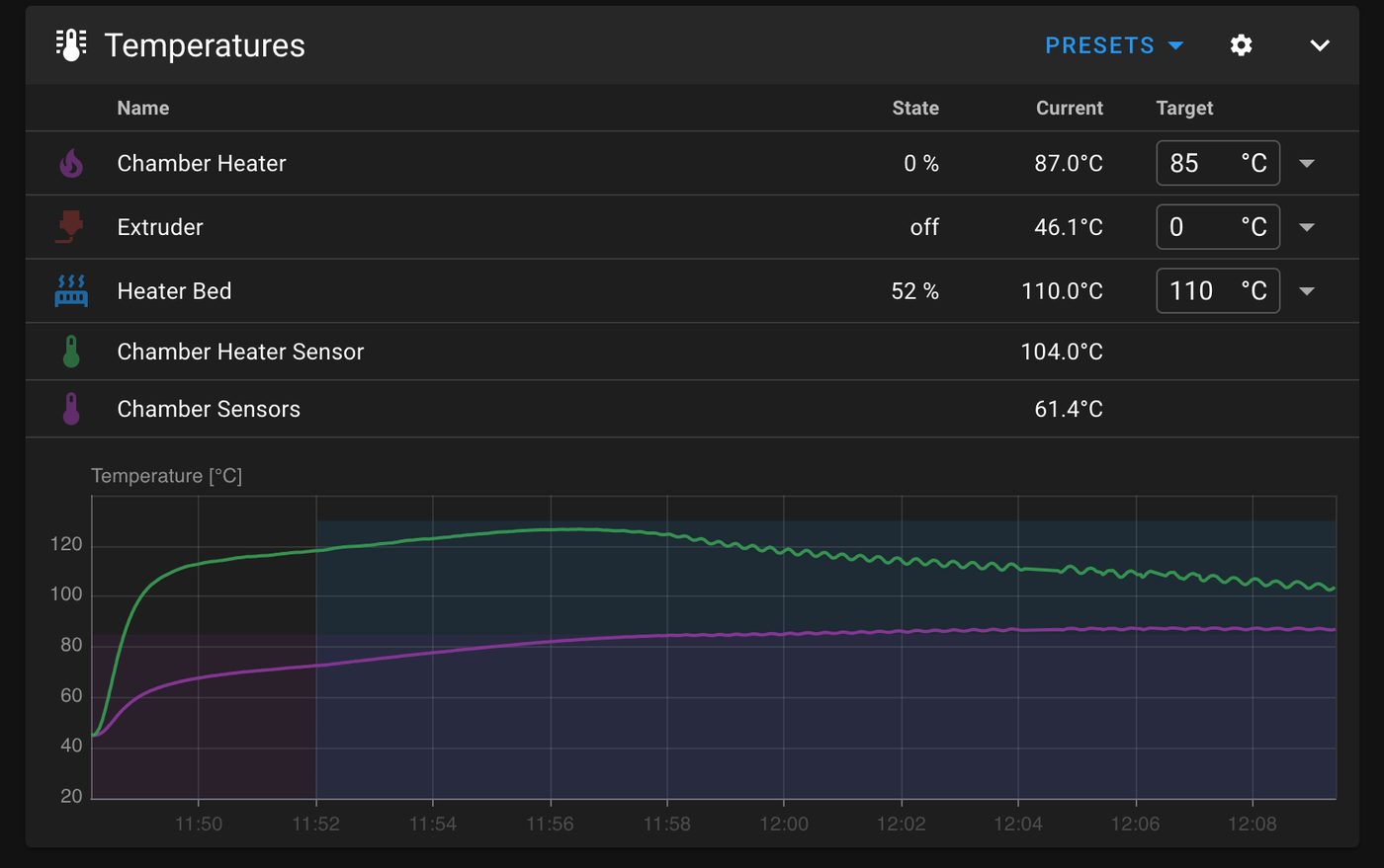
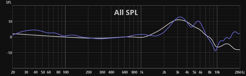
Temperature graph showing chamber and bed reaching steady state
FIG. A6
Klipper telemetry. Bed (green) climbs to 110 °C; chamber (purple) stabilizes at the 85 °C target within 15 minutes and holds.
02
Year
2024—25
Type
Personal · Acoustic Design
Tools
Fusion 360 · H.E.A.R.S · REW
Status
Built & measured

Open-back headphones, tuned by graph.

Why build them. Most off-the-shelf headphones cost $$$ for the wood cup and the brand. The driver itself is often the easy part. I wanted to learn the acoustic side — how the cup, the baffle, and the damping pattern shape what you actually hear — by designing and building the whole thing from scratch.

The cup. Walnut on the outside, a 3D-printed structural baffle on the inside. Wall thickness, internal volume, and the bevel angle behind the driver are all tuned to push resonant nodes out of the audible band.

The baffle. A printed spoke pattern that doubles as structure and as damping geometry — the spoke spacing controls how much air gets coupled to each part of the driver, which is the lever you pull to shape mid-treble.

Tuning loop · iterate baffle geometry until SPL converges
STEP 01 Print FDM baffle, ~2 hr STEP 02 Measure H.E.A.R.S sweep STEP 03 Compare measured vs target STEP 04 Adjust CAD spoke spacing & vol REFERENCE target SPL curve FEEDBACK · NEW BAFFLE GEOMETRY
Three iterations to converge near the target curve. No electronic EQ — every change happened in the printed baffle.
Finished open-back headphones with walnut wood cups
FIG. B1
Finished pair. Walnut cups, leather suspension strap, balanced cable.
CAD render of the printed acoustic baffle
FIG. B2
Printed baffle. Spoke geometry sets the damping pattern across the driver face.
CAD render of the wood cup with internal baffle
FIG. B3
Cup assembly. Walnut shell, printed baffle, internal volume tuned to push resonance out of band.
Inside view of the driver and printed baffle assembly
FIG. B4
Driver mounted in the printed baffle, viewed from inside the cup before sealing.
Headphones mounted on H.E.A.R.S measurement rig
FIG. B5
Measurement on a miniDSP H.E.A.R.S rig. Each iteration of the baffle gets a fresh sweep.
SPL frequency response measurement plot
FIG. B6
SPL response, 20 Hz–20 kHz. Blue trace is the final iteration; the lighter trace is the target. Noise above 8 kHz is rig-related, not driver behaviour.
03
Year
2024
Type
Team · MIE243 Capstone
Tools
SolidWorks · ANSYS · MATLAB
Status
Conceptual · A+

A hobbyist CNC router that cuts aluminum at 4×4 ft.

The gap. Hobbyist CNC routers come in two flavours: cheap toys that can't cut aluminum, or industrial machines priced out of a home shop. The team's brief was a router that fits in a one-car garage, costs under CAD $4,000, and actually cuts aluminum with a safety factor of 4.

My contribution. Force calculation and structural analysis. I derived the worst-case 280 N cutting force from spindle power, ran ANSYS static structural on the 4080 aluminum gantry, and confirmed a 12.5× safety factor before we committed to the extrusion size.

Final architecture. Y-moving gantry, dual SFU1605 ball screws on X and Y, T8 lead screw on Z, MGN12H linear rails on all three axes. The motion-system tradeoffs — backlash vs. cost vs. scalability — came from a weighted decision matrix across six candidates.

Bill of materials. 4×4 ft work area, ±5 µm theoretical resolution per microstep, CAD $3,717 total — all parts sourceable from Misumi, Hiwin, and McMaster.

SolidWorks render of the full CNC router assembly
FIG. C1
Final assembly. Aluminum extrusion frame, 4080 gantry beams, plywood spoilboard with T-slot channels for workholding.
12.5×
Gantry safety factor (ANSYS)
±5µm
XY resolution / microstep
$3.7k
BOM, under $4k budget
ANSYS total deformation plot of the gantry
FIG. C2
ANSYS Static Structural — total deformation. Max 35 µm at gantry mid-span under 280 N cutting load.
ANSYS safety factor plot of the gantry
FIG. C3
Safety factor map. Min 12.5× yield — comfortable margin for accelerating gantry mass.
Z-axis assembly with and without router head
FIG. C4
Z-axis assembly. Lead-screw drive (no brake required, self-locking thread profile), MGN12H linear guide, custom aluminum carriage plate sized to the Makita RT0701C router clamp.
04
Year
2023—Present
Type
Team · Aerospace
Tools
CATIA · ANSYS · Composites
Status
Active

Composite airframe panels for a liquid-propellant rocket.

The work. Designing non-structural composite airframe panels for UTAT's liquid-propellant rocket. Modular geometry that integrates with the propulsion bay and gives the test team rapid access during pre-launch — without compromising aerodynamic stiffness.

The simulation work. ANSYS FEA against flight loads — shaved 15% mass off the panels while meeting stiffness targets.

The manufacturing pivot. Pioneered the team's transition from positive to negative-mould fabrication for these panels. Halved production time (2 weeks → under 1) and gave us cleaner aerodynamic surfaces with fewer post-cure defects.

CAD render of the UTAT airframe section
FIG. D1
CATIA assembly. Carbon-fibre tube with internal aluminum hardpoints for module integration.
Real airframe section under assembly
FIG. D2
Assembled airframe with one panel removed for access. The panel-on-panel design halved setup time at the test stand.
Carbon fiber layup in process
FIG. D3
Wet-epoxy layup, mid-cure. The negative-mould transition meant pulling these tubes off a polished interior surface instead of fairing a positive — better aerodynamic finish, less post-cure rework.
05
Year
2025
Type
Personal · Precision Mechanism
Tools
Fusion 360 · Manual lathe (planned)
Status
CAD complete

A piston-filler fountain pen, designed for the lathe.

Why. A small, beautiful exercise in tolerance stacking and precision turning. The whole pen is a single linear mechanism — a piston riding inside a transparent reservoir, sealed by an O-ring, advanced by a threaded collar — but every dimension has to be right or it leaks, binds, or drips.

What's interesting. Designing for the manual lathe means thinking in operation order: which features get cut first, which surfaces become datums, where the tolerance has to live. The CAD looks simple. The setup sheet is where the engineering shows.

CAD render of the fountain pen showing the internal piston mechanism
FIG. E1
Sectioned CAD. Threaded piston, O-ring seal, transparent ink reservoir, and a turned aluminum cap.
06
Year
2024—In progress
Type
Personal · Mechatronics
Tools
Fusion 360 · Python · RPi
Status
In progress

A programmable macro camera slider for the kind of photos that need it.

What it does. A motorized linear slider for macro photography — a Raspberry Pi drives a stepper motor through custom Python software that automates focus stacks, panoramic tracks, and time-lapse shoots. Sub-millimeter positioning, zero step loss across 100+ continuous cycles in endurance testing.

Designed for FDM. Carriage and rail topology optimized for desktop 3D printing — 30% less filament than the first version, and stiffer where it matters: mid-span, where vibration becomes visible at long exposures.

Build status. Mechanism prototype is running; mounting hardware and the final electronics enclosure are still in progress.

Macro photograph of a U-notch fatigue specimen
FIG. F1
Output sample. Macro of a U-notch fatigue specimen, lit and stacked using the slider's automated focus-stack routine.

§ 02 / Experience

Where I've put it into practice.

2025
Han's Laser Technology Co.
Mechanical Design Intern
Engineered automatic clamping systems for steel-panel laser welding using pneumatic actuation and guide rails — eliminated manual alignment and cut shop-floor setup by 20 minutes per batch. Diagnosed misalignment in prototype trials and redesigned gantry rails to resolve tolerance stacking. Owned SolidWorks production drawings and BOMs for the assembly team.
Shenzhen, CN
2023—Now
University of Toronto Aerospace Team
Aerostructures Designer
Composite airframe panel design for a liquid-propellant rocket. ANSYS-driven structural optimization (15% mass reduction) and a transition to negative-mould fabrication that halved panel production time.
Toronto, CA
2023—Now
University of Toronto
BASc Mech. Eng. + PEY Co-op
Specializing in Mechatronics and Solid Mechanics; minor in Engineering Business. Coursework: Mechanical Design, Mechatronics Systems, Mechanics of Solids (FEA), Manufacturing Engineering, Computational Fluid Dynamics.
Toronto, CA

§ 03 / Skills

What I reach for, in order.

Design & Simulation

  • SolidWorks daily
  • Fusion 360 daily
  • CATIA proficient
  • ANSYS — FEA proficient
  • ANSYS — CFD working
  • GD&T (ASME Y14.5) proficient

Code & Controls

  • Python proficient
  • MATLAB proficient
  • G-code / CAM working
  • Klipper firmware working
  • Raspberry Pi / Arduino working
  • Git / GitHub working

Manufacturing

  • FDM 3D printing expert
  • Composite layup proficient
  • Pneumatic systems proficient
  • CNC milling — manual ops working
  • Laser cutting working
  • BOM & ECN documentation proficient

§ 04 / Contact

Get in touch.

I'm looking for a 12-month PEY co-op starting September 2026, in mechanical design, mechatronics, or manufacturing engineering. Best reached over email — I'll get back within a day.